As you may or may not have noticed, Alex skimps on the details of Workshop #1. This was because the ‘copious amounts of chocolate’ were mainly consumed by him, while myself and Simrun actually did something productive!
The GPS
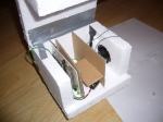
First stop was the GPS. The longest part of the whole shenanigans was wiring the damned thing up. We started by testing the wire that the GPS had come with, but found to our dismay that one of the pins had become unconnected – bad news! (Remember, the iQ blows up, doesn’t work or breaks itself if you don’t wire correctly!) So we got the scissors and stripped all of the stuff off until all we had was the pinheader. I then proceeded to poke wires into each hole and then attach it to some part of the breadboard in such a way that the tension on the wire kept it connected nicely. The result was this pictured spidery mess of fail that is perhaps the greatest insult to all that is sane electronics. Ah well.
Next step was connecting the pins. Starting simple, we decided to use the NMEA output, which is on pin 5. We ignored pin1 (which outputs Trimble’s binary protocol), and followed the manual and pulled pin3 and pin6 upwards to vcc (pin7). (pin3 and pin6 are the RX pins. Failure to pull these up [we used a 10k resistor] results in breaking the GPS unit – or worse). Finally we attached pin2 to the ground, and used the 3.3v regulated output on the Arduino to give power to pin7.
Next, I attached pin5 (the output that we were interested in) to the Arduino’s pin1. While this may seem wrong (pin1 is the TX pin of the Arduino, not the RX), we didn’t actually want to transmit to the ATmega – instead, we programmed the mmcu to ignore all serial data, and the info from the GPS went straight to the FTDI usb-to-serial chip and then to the usb. Basically, the Arduino TXs on pin1, which goes out of pin one AND to the FTDI chip – pin1 is connected to the FTDI chip’s RX. So connecting the GPS to pin1 resulted in the GPS being passed-through to the FTDI.
Then it was the moment of truth. The TX light flashed on the Duemilanove board… yet nothing happened. We had the baudrate wrong!
Here’s the command we used to get it all right. We were using Simrun’s Ubuntu desktop, this is a linux command. But for reference, the baudrate of the Lassen iQ’s NMEA is 4800.
stty -F /dev/ttyUSB0 cs8 4800 ignbrk -brkint -icrnl -imaxbel -opost -onlcr -isig -icanon -iexten -echo -echoe -echok -echoctl -echoke noflsh -ixon -crtscts
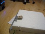
SUCCESS! Well, sort of. We were getting lines of text in our terminal every second, and the GPS was telling us that it had no fix yet. So, we dangled it out of the window and waited – finally, in NMEA it reported our location, which we won’t share here, but we checked on Google Maps and it was correct and precise. Win!
The next step involves getting a proper cable to connect the Lassen iQ to the final setup. We intend to use the recommended (by Trimble) Samtec FFSD-04-S-6.00-01
The Camera
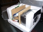
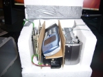
Alex and Simrun were a bit cautious taking apart the camera, however I went ahead and removed every screw in my way to great success! We fully detached the top of the camera leaving the buttons and their solderable legs exposed… although I’m not sure how well it will go back together. We spent atleast 15minutes messing around with a length of wire, shorting terminals together to produce interesting effects including taking photos, zooming, focusing and turning on and off. I will solder to those legs tomorrow and get the Arduino ready to control the camera. I’ve annotated the picture to show which pin does what.
-

-
Overview of the GPS-Breadboard fail
-

-
GPS and breadboard half-way out of the window
-

-
Camera with the top cover off and ciruitry de-fastened
-

-
With annotations
Important Links (for the GPS)
The Lassen iQ Manual: Pages (24) 34, (28) 28 and (230) 240 are of extreme interest. (Numbers in brackets are Trimble’s bottom-left numbers, start 10 pages late due to 10pages of contents. Other numbers are the page-numbers that my PDF reader sees).